




LED heat dissipation plays an important role in the reliability, lifespan, and safety of a Night Light Plug. Although plug-in Night Lights typically consume less power than conventional lighting products, the LED chip, driver circuit, and internal electrical components still generate heat during operation. If this heat cannot escape efficiently, temperatures inside the compact housing may rise, accelerating component aging, reducing light output, and increasing the risk of premature failure.
For overseas importers, wholesalers, retailers, and OEM buyers, evaluating thermal performance requires more than checking LED wattage or advertised lifespan. Housing design, PCB layout, thermal interface materials, soldering quality, component selection, and production testing all influence how effectively heat moves away from the LED junction. Understanding these factors helps buyers assess product consistency and identify manufacturing issues before they lead to customer complaints.
Why LED Temperature Matters in a Plug-In Night Light
An LED converts electrical energy into light, but some of the energy is released as heat. The LED junction temperature rises when heat generation exceeds the rate at which heat can travel through the package, circuit board, and surrounding structure into the environment.
Excessive junction temperature can accelerate degradation of the LED semiconductor, phosphor, encapsulant, and nearby electronic components. Over time, the light may become dimmer, color output may shift, or the LED may fail prematurely. Elevated internal temperatures can also affect driver capacitors and other components, particularly in compact products with limited ventilation.
The challenge for a Night Light Plug is its small enclosure. Unlike a larger luminaire, it has limited surface area and little room for a dedicated heatsink. Thermal performance therefore depends on efficient heat transfer through the LED package, PCB, internal mounting structure, and outer housing.
Manufacturers must balance thermal management with electrical safety, compact dimensions, appearance, and production cost. A design that uses a high-output LED in a small enclosure without sufficient thermal evaluation may achieve the desired brightness initially but struggle to maintain consistent performance during extended operation.
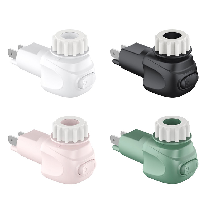
How LED Package Selection and PCB Design Affect Heat Transfer
The thermal path begins at the LED junction and continues through the LED package into the PCB. The thermal resistance of each part of this path determines how much the junction temperature rises above the surrounding reference temperature for a given heat load.
LED package design, solder-pad geometry, PCB copper thickness, and board construction all affect heat transfer. A board with an unsuitable copper layout or insufficient thermal spreading area can create a localized hot spot beneath the LED, even when the total electrical power is relatively low.
For compact plug-in lights, manufacturers may use conventional FR-4 boards or other PCB constructions depending on the design and thermal requirements. The appropriate choice depends on LED power, available space, cost targets, and the intended operating temperature. A metal-core PCB may improve heat spreading in some designs, but it is not automatically necessary for every low-power night light.
During PCB design, engineers should evaluate the placement of LEDs, driver components, copper areas, and thermal vias where applicable. Keeping heat-sensitive components away from major heat sources can also reduce localized temperature stress.
Manufacturing quality is equally important. Variations in copper thickness, board dimensions, solder-pad geometry, and component placement can alter the thermal path. Design verification should therefore include thermal measurements on representative assembled products rather than relying exclusively on theoretical calculations.
Why LED Soldering Quality Influences Long-Term Reliability
The solder joint between an LED and its PCB provides both an electrical connection and, depending on the package design, an important path for heat transfer. Incomplete wetting, voids, insufficient solder, or excessive solder can compromise the joint's electrical or thermal performance.
For surface-mount LEDs, the reflow soldering process must follow a suitable temperature profile. Preheating, peak temperature, time above liquidus, and cooling rate affect solder formation and component stress. An unsuitable profile can produce weak joints, component damage, or inconsistent assembly results.
Incorrect solder-paste volume and PCB pad design can also contribute to voiding or uneven contact. These defects may increase local thermal resistance, causing the LED junction to operate at a higher temperature than expected.
Manufacturers should establish validated soldering parameters and monitor process consistency. Automated optical inspection can detect component misalignment and visible solder defects, while X-ray inspection may help evaluate hidden joints when the package structure warrants it. Process audits and electrical checks provide additional evidence, but neither visual inspection nor electrical continuity alone proves that the LED has an adequate thermal connection.
How Housing Materials and Enclosure Design Control Heat Dissipation
The outer housing is part of the thermal management system. Heat must move from the LED and PCB through internal structures before reaching the housing surface and surrounding air. Housing material, wall thickness, internal spacing, and contact between components influence this process.
Plastic is widely used in plug-in night lights because it supports compact shapes, insulation, and cost-effective production. However, ordinary plastics generally conduct heat less effectively than metals. If the internal structure traps heat around the LED, the temperature may continue rising during extended operation.
Manufacturers can improve thermal performance through suitable internal component placement, effective contact between the PCB and designated heat-spreading structures, and careful control of enclosure geometry. Ventilation openings may help in some designs, but they must not compromise electrical insulation, protection against accidental contact, or applicable safety requirements.
Material selection also affects dimensional stability and aging. Excessive temperatures can contribute to discoloration, deformation, or deterioration of unsuitable plastics. Injection molding conditions, wall thickness variation, and assembly tolerances may change the internal clearances and thermal contact between components.
During development, engineers should assess both internal hot spots and accessible surface temperatures. The objective is not simply to maximize heat transfer but to maintain acceptable LED junction temperature while ensuring that the finished product meets applicable electrical and thermal safety requirements.
Driver Circuit Heat Can Accelerate LED Failure
The LED is not the only heat source inside a Night Light Plug. The driver circuit may generate heat through switching losses, rectification losses, resistive losses, and other conversion inefficiencies. Because the driver and LED share a small enclosure, heat from one can raise the operating temperature of the other.
Driver component selection must account for electrical stress and thermal conditions. Capacitors, rectifiers, resistors, and switching devices should be rated for their actual operating environment, with appropriate margins for voltage, current, temperature, and expected service life.
For example, an electrolytic capacitor exposed to persistently elevated temperatures may age faster, potentially affecting driver stability and product lifespan. Poor component spacing or placing a heat-generating resistor too close to a temperature-sensitive part can further increase thermal stress.
Manufacturers should evaluate the complete assembled circuit rather than measuring LED temperature in isolation. Thermal imaging can help identify surface hot spots, while thermocouples can measure specific component temperatures. Electrical tests should also verify that the driver maintains stable output under the intended input-voltage and operating conditions.
How Production Testing Identifies Thermal Problems
A Night Light Plug may pass a brief functional test while developing excessive heat after several hours of operation. Thermal validation must therefore evaluate the product after temperatures have had sufficient time to approach a stable operating condition.
During engineering validation, the product should operate at its specified input voltage and representative environmental conditions. Engineers can record LED board temperature, driver component temperatures, and relevant housing surface temperatures. Where direct junction-temperature measurement is impractical, an appropriate validated estimation method may be used.
Testing should cover the operating conditions most likely to produce the highest thermal stress. These may include upper input-voltage limits, elevated ambient temperature, continuous operation, and representative production variations. The exact test conditions should follow the product specification and applicable safety requirements.
Thermal imaging is useful for locating hot spots, but emissivity differences and surface reflections can affect readings. Contact sensors can provide more direct measurements at selected points. Reliable evaluation requires suitable sensor placement, calibrated equipment, repeatable test conditions, and documented acceptance criteria.
Production quality control should also connect thermal findings with manufacturing records. If certain batches show higher temperatures, investigators should review LED specifications, soldering profiles, PCB construction, driver components, and housing tolerances. Correcting the underlying process variation is more effective than relying solely on additional inspection.
What B2B Buyers Should Evaluate Before Placing an Order
For importers, distributors, and private-label brands, thermal performance should be part of the supplier qualification process. A product's advertised LED lifespan does not automatically establish the service life of the complete plug-in night light, because the driver, insulation materials, solder joints, and enclosure also influence reliability.
When evaluating a Night Light Plug supplier, buyers should consider the following technical information:
Thermal design: Ask how the LED, PCB, driver, and housing are designed to manage heat during continuous operation.
Component specifications: Confirm LED operating limits, driver component ratings, and the suitability of housing materials.
Thermal test reports: Request documented temperature measurements under defined operating and ambient conditions.
Production consistency: Review soldering controls, PCB inspection procedures, component traceability, and finished-product testing.
Safety compliance: Verify applicable electrical and thermal safety documentation for the intended destination market.
Customization validation: Ensure that changes to LED power, housing geometry, PCB design, or driver components trigger appropriate re-evaluation.
These checks are especially important for OEM projects. A housing redesign or brighter LED may change the thermal balance even when the external dimensions remain similar. Buyers should request validation data for the actual production configuration rather than relying exclusively on reports from a previous model.
Frequently Asked Questions
Can poor heat dissipation shorten the lifespan of a Night Light Plug?
Yes. Elevated LED junction and driver component temperatures can accelerate material degradation and electrical component aging, potentially shortening the lifespan of the complete product.
Does a brighter LED always generate more heat?
Not necessarily in direct proportion to brightness. Heat generation depends on electrical input power, LED efficiency, operating current, and thermal design. A higher-output LED may require additional thermal evaluation even when its efficiency is improved.
Is a metal housing always better for LED heat dissipation?
No. Metal can spread heat effectively, but housing selection must also consider electrical insulation, accessibility, corrosion resistance, mechanical design, cost, and safety requirements. A well-designed plastic enclosure can be suitable for a low-power night light.
What is the most important thermal test?
Steady-state thermal testing under defined operating and ambient conditions is essential. Engineers should measure relevant internal component temperatures and accessible housing surfaces, then compare the results with component limits and applicable product safety requirements.
Conclusion
LED heat dissipation directly influences the reliability of a Night Light Plug through its effects on junction temperature, driver component aging, solder-joint performance, and housing durability. Effective thermal management depends on coordinated PCB design, component selection, soldering control, enclosure engineering, and sustained-operation testing.
For B2B buyers, evaluating these factors provides a stronger basis for supplier selection than brightness and advertised lifespan alone. A well-validated design, combined with consistent manufacturing and documented thermal testing, helps reduce premature failures and supports reliable long-term product performance.
